Two years ago, I heard that “You can enjoy satellite band with GP antenna.” and after a lot of struggle, it’s only been about six months since I was able to contact via satellite.
During that time, I haven’t made any effort to improve my radio equipment for satellite use. But once I start satellite operation with a GP antenna, I soon realize that there are situations for which I absolutely must be aware.
The beam pattern of a vertical omnidirectional antenna such as a GP antenna is roughly this:
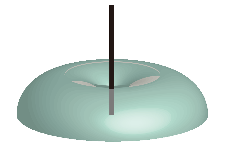
In other words, “a GP antenna is not good at working in the direction where the satellite signals are strongest, flying directly above me”. I wanted an antenna that flies directly above, so I made a 2-element turnstile antenna. This “2-element turnstile antenna” is a horizontal cross-shaped turnstile antenna that feeds dipole antennas in two orthogonal directions with a phase difference of 90°, with a reflector also arranged in a cross shape on the ground side. In the end, it is the same as a “vertically fixed 2-element cross Yagi antenna.” The beam is only directed directly upwards.

If I could effectively switch between these two types of antennas, I would end up with an antenna system that could cover almost the entire sky, like the one below…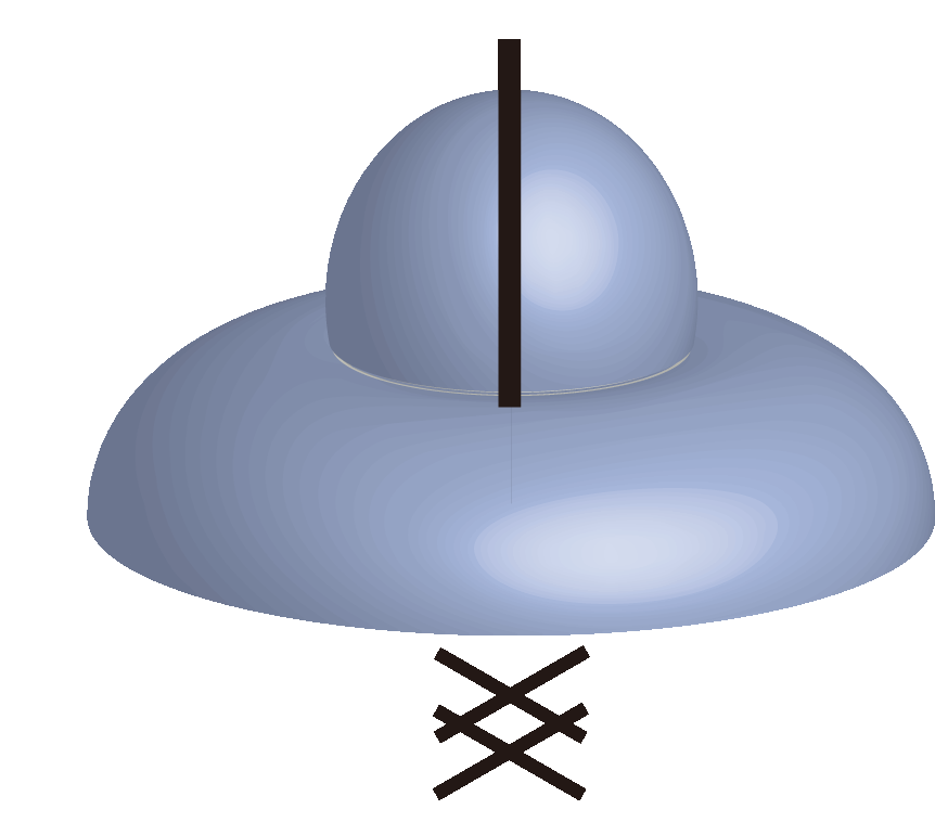
Currently, B mode and J mode are commonly used for satellite communications. B mode transmits at 435 MHz and receives at 145 MHz. J mode is the opposite.
Therefore, if we want to transmit in both modes, we will need to make one turnstile antenna for 145 MHz and one for 435 MHz. Since they will be facing upwards anyway, I attached them all to the same pipe.
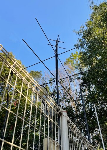
Paired with these two antennas is the white 144/430MHz compatible GP you can see in the back, and another one of the same. (Not visible in the photo) How do you switch between a total of four antennas with only about 10 minutes per path? I’ll try to figure out how to do this by using two duplexers.
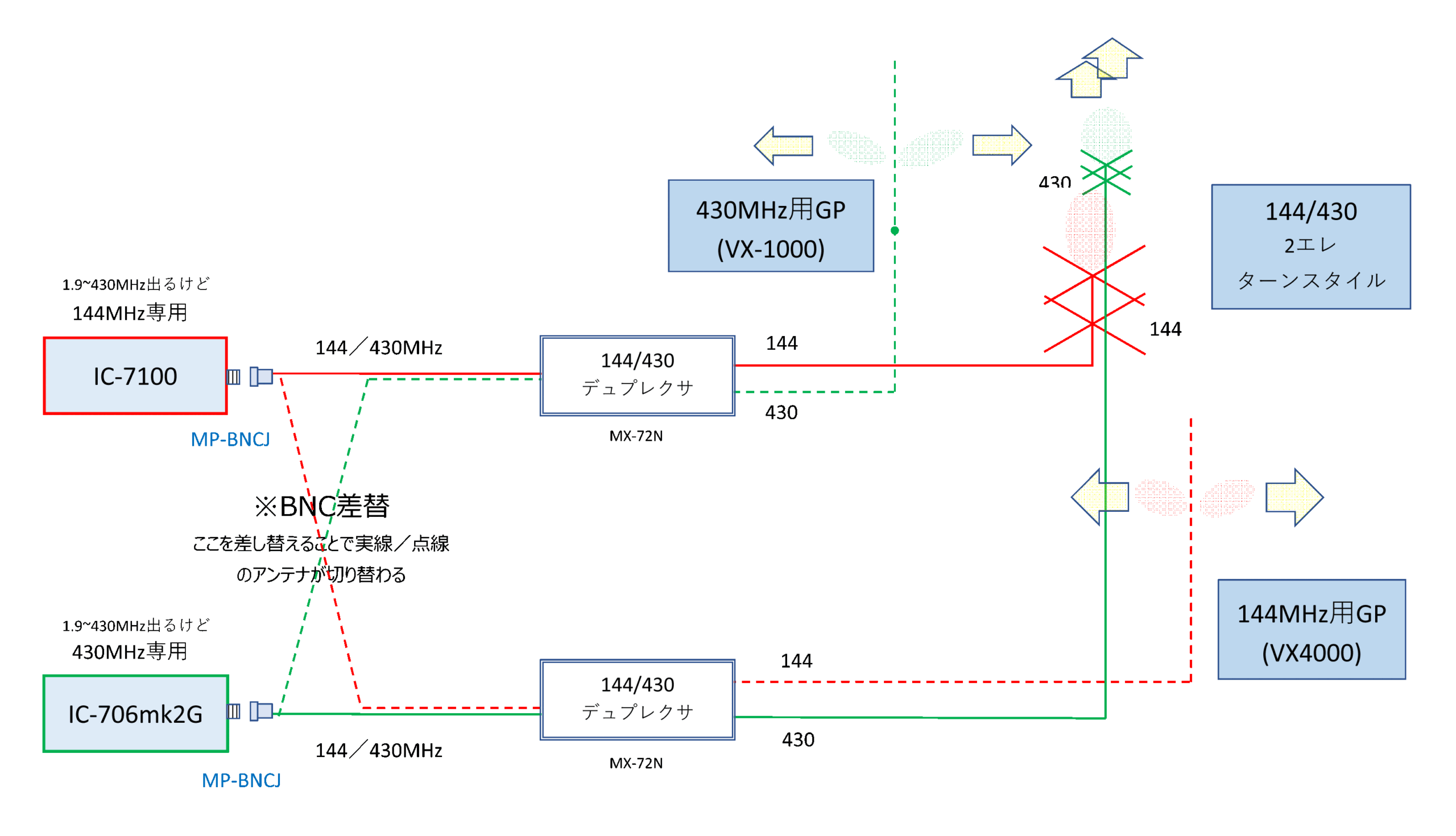
If I connect with a solid line, both transmission and reception will be connected to the turnstile antenna, but if I connect it in reverse and use the dotted wiring, both transmission and reception will be GP antennas.
The IC-7100 is for 144 MHz only, and the IC-706mk2G is for 430 MHz only.
The control unit of the IC-7100 is separate, so feel free to “turn the main unit around” so that the antenna connector is directly in front.
The IC-706mk2G can receive at 430 MHz, so I used the 144/430 duplexer as a filter and extension connector and brought it directly in front in the same way, and used conversion connectors to convert both M connectors to BNC.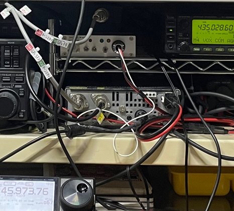
It takes about 5 seconds to replace the two antenna cables. It seems a little long for satellite communication, where each communication lasts about 10 seconds, but it’s a good thing that I don’t have to sit around and listen to the fade-out. In fact, since there is gain, I have to reduce the output accordingly.
Since the installation of the IC-7100, the IC-706mk2G has been practically written off and removed from the construction specifications, but he has finally returned to active duty. It once spanned the seven seas (or maybe three…), now space.
JARD has guaranteed it as a 100W technically-compliant model, but in reality he will work on 430MHz and output only 10W for the rest of his life.