At least as a fixed beam…
For those living in apartments, an HF beam antenna is a dream.
From the train or car window, I sometimes see fellow enthusiasts with antennas set up at unreachable heights and at unaffordable prices, and just stare at the passing scenery with my fingers in my mouth. (Oops, drive safely…)
But I’m not completely new to beam antennas. When I was a university student, I had a 21MHz Swiss quad set up at my parents’ house. It was a product of Taniguchi Engineering Traders (TET), which no longer exists, and it was an antenna with great range that allowed me to get KP4AM/D (Deseceo Island) in the Caribbean by calling only twice.
I can’t set up HF Swiss quad home, but 430MHz SQ is small, so I think I could stack it. If I aimed the beam towards Mt. Tanzawa or Mt. Fuji (well, I can’t see either of them), it might get scattered by the housing complex in front and fly off to a surprising place?
Even such a shallow assumption can be a driving force for making an antenna. Speaking of 430MHz Swiss quad ), there is the MK-4WD from the Kanagawa Ham Center, but I wasn’t confident that I would be able to make full use of it after spending so much money on it, and it happened to be “sold out. Next shipment undecided,” so I thought, “Oh well, I’ll just make one myself!”

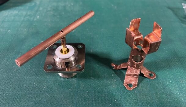
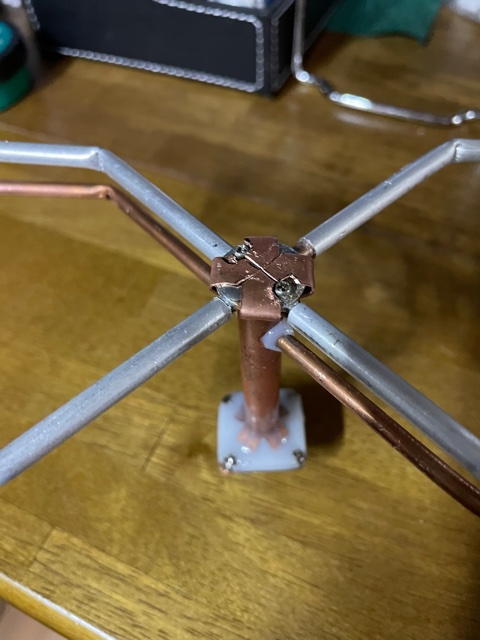
The keystone of Swiss-Quad is this central point. The old ready-made products were also machined aluminum and had exquisitely shaped cross mounts…looking back, it was clear how much effort went into making them. Here, copper pipes were welded together to create a flat cross, and copper washers were fastened with screws on both sides.
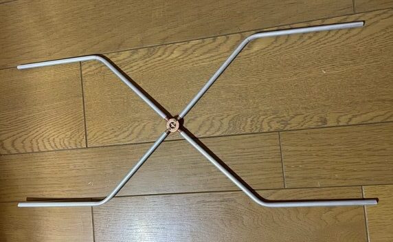
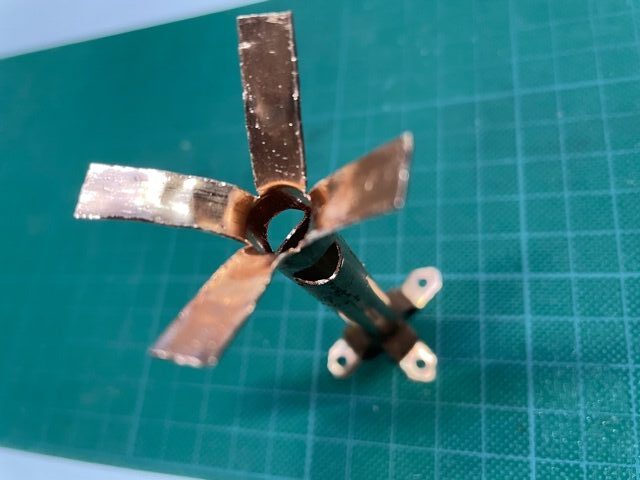
The quality of the bending process affects the overall precision, so each part only has one bend. Bend as accurately as possible to 45 degrees, and then cut both ends evenly using the corner as a reference.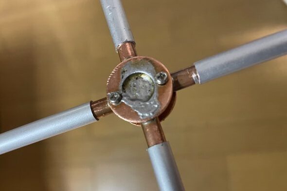
The intersection of the elements is soldered together.
Next I created the matching section. I used an M-R square base and a copper pipe. At first I was cutting the copper pipe with a Piranha saw, but it got tiring so halfway through I started cutting it with pliers. 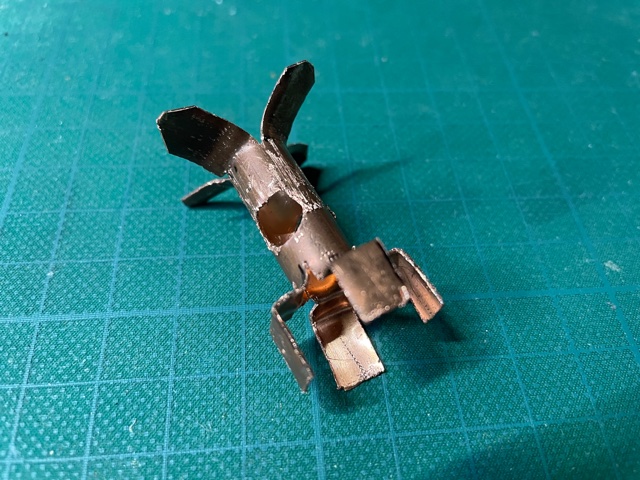
It’s a bit of an unidentifiable shape…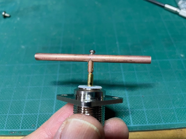
This will be the base of the phase line.
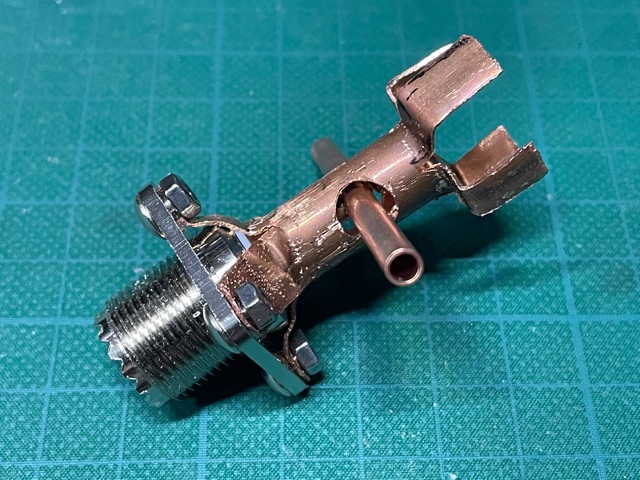
Let’s combine these two.
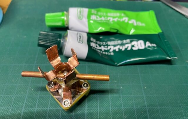
Fill the gap with epoxy adhesive. Create a bank around the M-R corner seat using masking tape.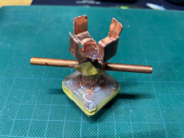
Once the epoxy adhesive has spurted out from the base like this, let it harden.
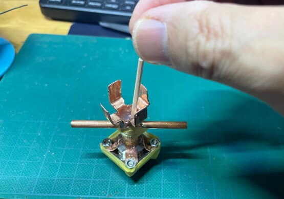
??? Hmm, with these arm lengths I can’t lay it down and install it for vertical polarization… It’s a design flaw.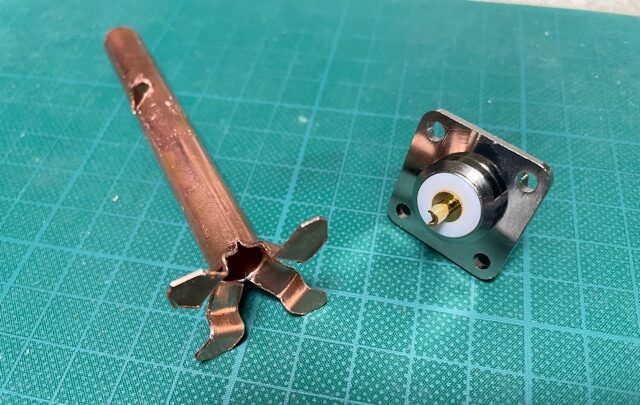
I made it longer and recreated it.
This time, pour the epoxy in from the side. The T-shaped part of the core wire is soldered in advance. Just to be safe, the coaxial part of this copper pipe has a calculated resistance of around 50 ohms.
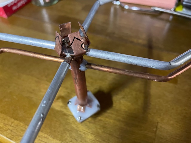
The element is integrated with the intersection to which it is attached.

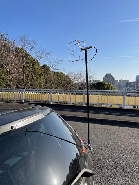
I put an MP connector on the VP13 socket, put it on the mobile base and check the flight. Of course, it won’t run the car in this state. I entered it in a local UHF contest, and it flew pretty well all over the Kanto area.