The circuit diagram looks like this.
The motor with speed reducer is 5 rpm, but to track a low-orbiting satellite, it takes about 15 minutes for an azimuth angle of 180° from AOS to LOS. This means that to slow it down to 30 minutes per rotation (= 0.033 rpm), a further reduction ratio of 1:150 is needed.
When tracking with a rotator is done manually, you would briefly push a lever of the rotator-controller at regular intervals, so this circuit does exactly the same thing. In other words, all we need to do is operate this motor intermittently with an ON:OFF ratio of 1:150, which can be achieved with a timer circuit.
I cited an article on making an intermittent timer from “Karioka’s Laboratory” (https://blog.goo.ne.jp/carioca_lab) and made the control circuit by replacing it with parts I had on hand.
Actually, if the OFF time is too long, it will not track the satellite, so I aim for an ON:OFF ratio of about 0.4 seconds:60 seconds. If it’s 5 rpm, then the rotation angle in 0.4 seconds is 12°, and it should rotate 180° in 15 increments. This should be just right.
The circuit is fairly simple, but when we tried to implement it inside the VP20, it ended up being long and thin like an eel’s bed. So I divided the circuit into three units: (1) the battery section, (2) the control circuit section (to the left of the relay), and (3) the motor drive section.
 This is the motor drive part (3).
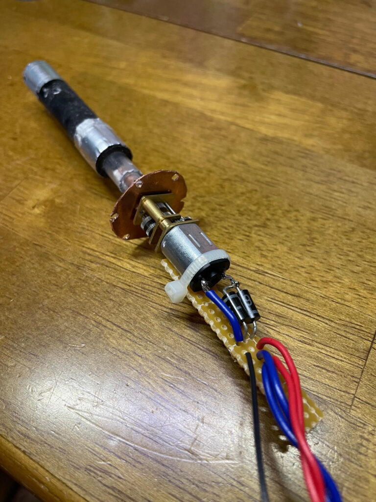
Since the antenna swings, if it hits an obstacle and stops moving, the motor itself will damage itself due to its own power.
For this reason, the 3Φ motor shaft is first supported by a 4Φ copper pipe, and then aluminum 5Φ-aluminum 6Φ-ABS 8Φ-ABS 12Φ are used to transmit torque using friction alone.
This “bamboo shoot” (top left in the photo above) seems to slide and rotate when I twist it with all my might, so this should be fine.
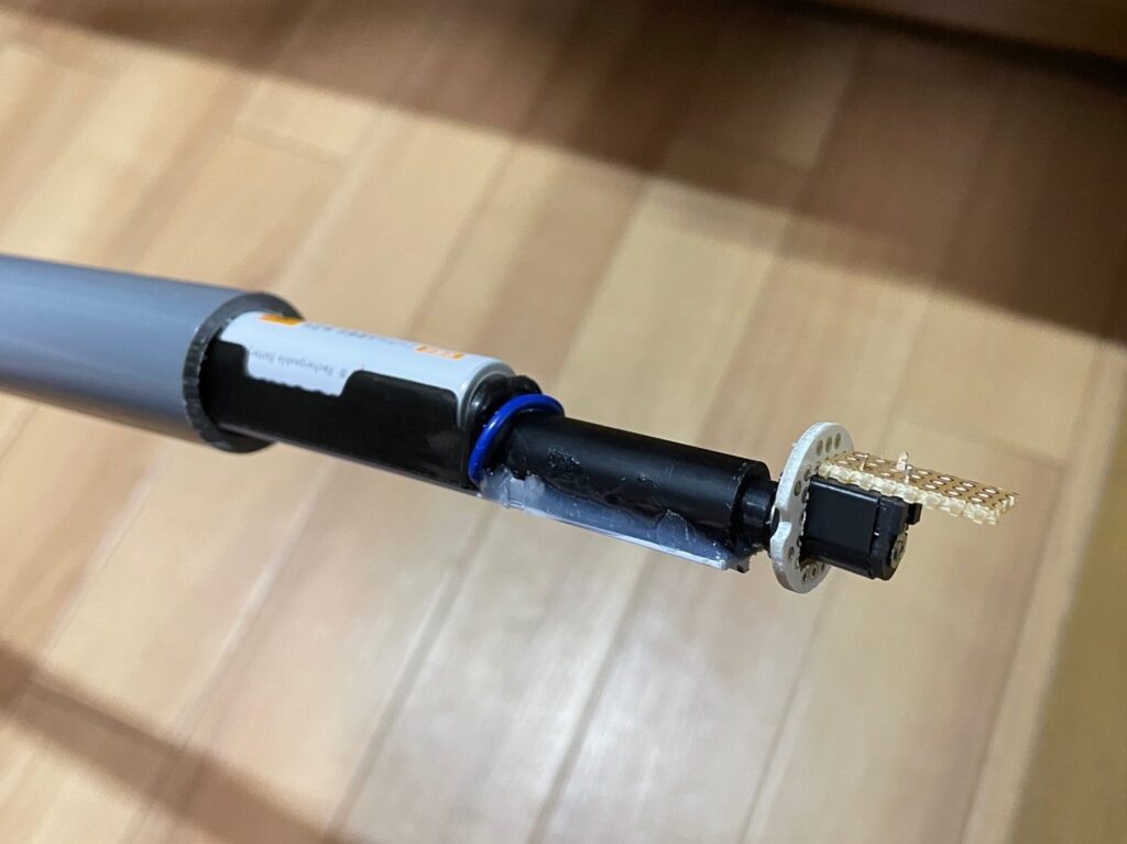
This is the battery part of (1). Line up the DC plug and the holder for two AA batteries in series, then buy a piece of ceiling trim from a home improvement store and use this as a base and attach it with double-sided tape or epoxy adhesive to combine them into one unit.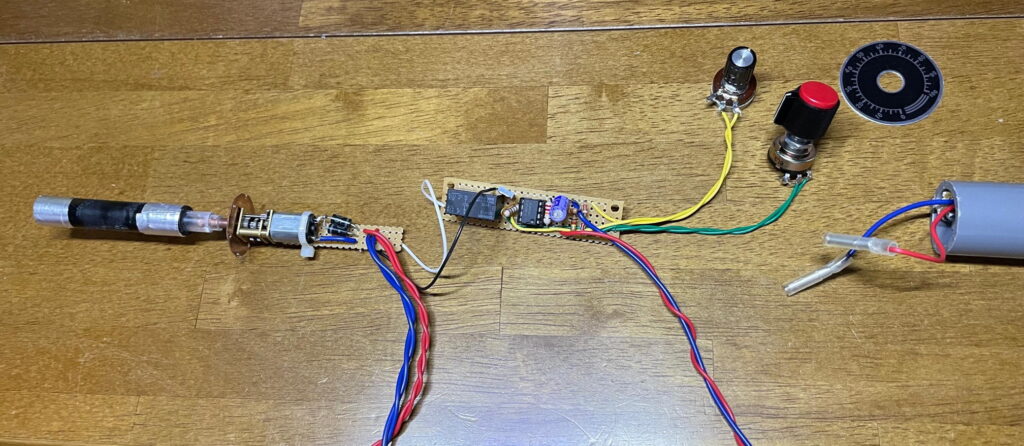
It looks like it could be built into the VP20. I tried running it in this state.
Watch the youtube video here
It seems to work fine somehow. Let’s try to implement it.
It goes in surprisingly well. The Upper photo is the base of the rotator with the battery unit inside. The lower is an M-type plug that was about to be disposed of, glued into the VP13 socket. (The size is perfect. )
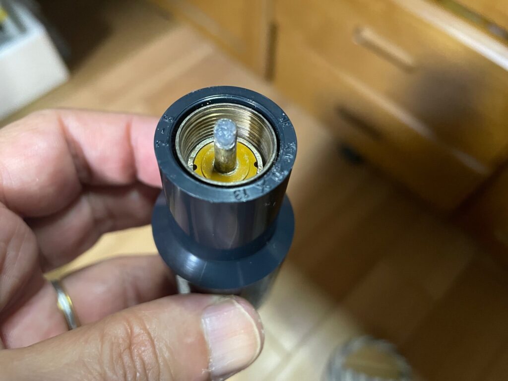
Power feeding to the antenna is via a separate 3D2V cable, so this plug is a structural material for screwing in that has nothing to do with feeding.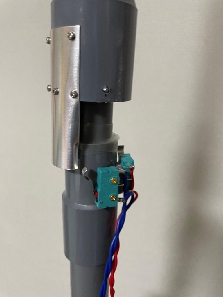
Using a microswitch and an aluminum plate, I have created a limit switch that can be turned off in just half a turn.
→To the next page (Vinyl Pipe Rotator for Amateur Satellite Part-4)
→Back to Index