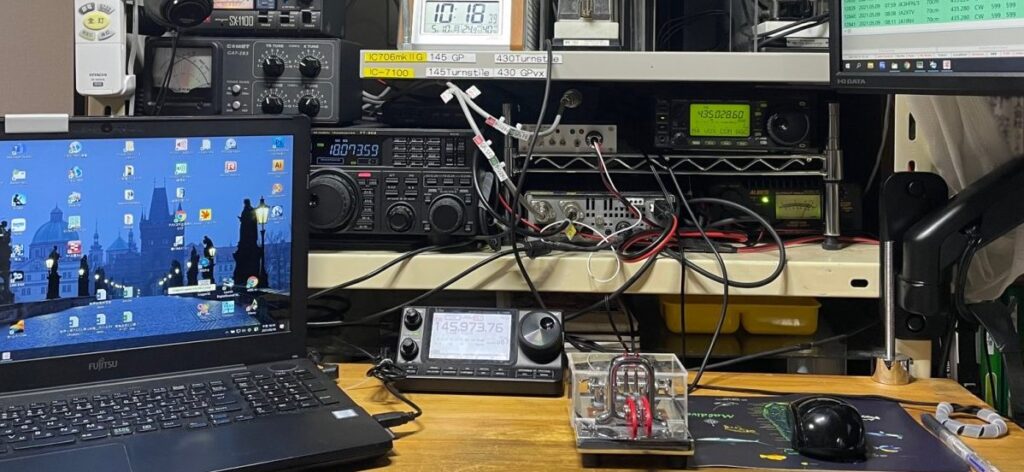
Now, when I’m working on the radio at home, I have my laptop on my desk, so I can always use two separate radios for sending and receiving plus the computer screen in an environment that’s easy to see.
It looks like this. Well, it’s fairly neat, so the computer can be used.
On the other hand, if you try to operate satellite ham radio from a car… (Strangely enough, I feel like doing it for some reason.) It looks like below.
It’s chaos. 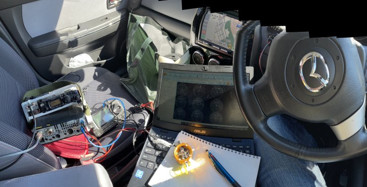
The PC I am relying on for satellite tracking has an LCD screen that is almost impossible to see in direct sunlight, and since it’s a secondary PC, the screen is small at 11 inches… there’s no way I could do both satellite tracking and log bookkeeping at the same time…
So, we started a project to “try to break away from today’s dependency on computers and do satellite tracking.”
I. Let’s make the antenna track automatically without relying on a computer → “VP Rotator”
II. Let’s make a tool that can calculate the complicated frequency relationships of satellites in analog → “Satellite Slide Rule”
So that’s how it was.
-・・・-
After all, I’ll show you the deliverables: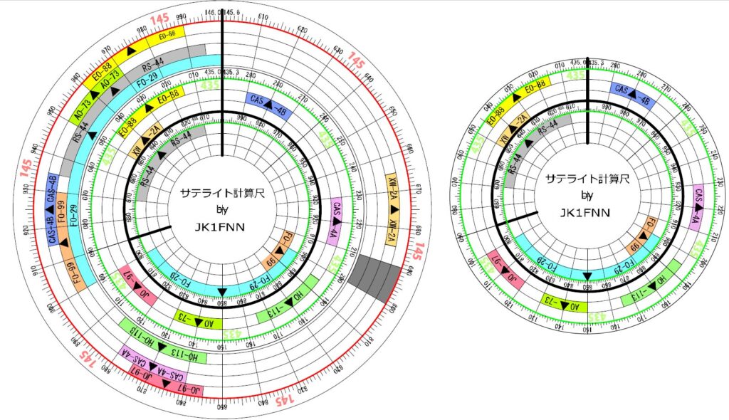
This was drawn using the free CAD software and in fact the small circle on the right is exactly the same as the one on the left, or rather it is actually unnecessary. The finished appearance looks like the photo below.
On the left, the largest concentric circle Red = 145MHz band and each satellite frequencies
Double line = A gap here, separating the inner and outer disks
Inside double line = Same as the right circle Green = 435MHz satellite band
And the frequency distribution is in the opposite direction, inside and outside.
So far,
(1) Find the approaching satellite among the bands of the inner and outer circles (the ones that are the same color),
(2) Align the center frequency of each band on the inner and outer disks (marked with black triangle) with the line that passes through the center of the concentric circles.
After doing this, if you slightly move the line that passes through the center to a certain receiving frequency, the scale on the other disk will be the corresponding transmitting frequency. However, Doppler shift is not yet taken in account .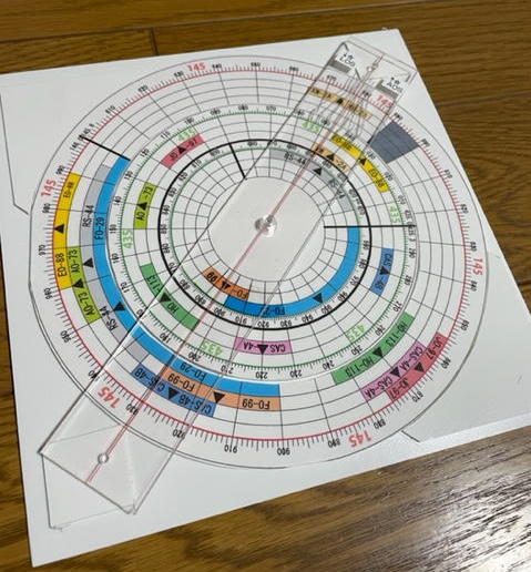
To estimate the Doppler shift on this slide rule, we need to modify the “straight line passing through the center.” In other words, since the inner 435 MHz frequency has three times the shift in the inverse heterodyne, we can put the previous straight line in the center and draw an auxiliary lines in the picture below. I’ll use the B-mode satellite, EO-88, as an example.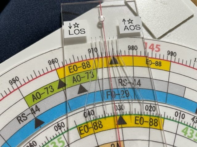
Align “▲” of the EO-88 transmission and reception center frequency (DOWN = 145.975MHz and UP = 435.030MHz) with this red line, and shift the red line scale within this yellow EO-88 band, but the amount of Doppler shift is enough to cover “at most ±3kHz at 145MHz, and ±9kHz at 435MHz”.
So, draw lines so as auxiliary scales. (The lines on the transparent acrylic board are those.)
Now, the EO-88 satellite (B mode) is rising across the horizon (AOS), and just when you think it has risen quite a bit and the downlink is strong enough, you hear “CQ SAT DE JQ1YLK” on 145.975MHz. Where should you transmit at this time? Use the second line from the right on the AOS side and align it to 145.975 The lower line will be about 435.026MHz.
Using the above photo and following the logic,
(1)Align the second line from the right (+2kHz) with the receiving frequency of 145.975MHz.
(2)At this time, the downlink radio wave emitted by the satellite is actually 145.973MHz on the red line. Since it is approaching, it is shifted + from here.
(3)The receiving (uplink) frequency that corresponds to the 145.973MHz transmitted (downlink) by the satellite’s transponder is 435.032MHz.(Follow the red line downward)
(4)To have the approaching satellite receive the 435.032MHz, you just need to transmit from the ground at a frequency lower than the Doppler shift amount.
(5)The Doppler shift at this time in the 435MHz band is three times 145MHz, or 2kHz x 3 = 6kHz. So you should transmit at 435.026MHz.
This corresponds to the scale drawn below the line in (1). If you transmit at this frequency, you’ll be able to monitor the downlink of your own waves as an audible sound without being too far off. (In J mode, the AOS and LOS in the photo are reversed.)
Since making it, I’ve been trying to use it as little as possible without relying on a computer, and it’s quite easy and convenient.
With the completion of this “Satellite slide rule” and the “VP Rotator” ,the satellite’s “ANALOG TRANSFORMATION” is now complete.
(April 25, 2022)
→Back to Index